@wangfei9088 在 rhoPimpleFoam求解器中EEqn.H能量方程具体形式是什么? 中说:
@AppleKiller $\nabla \cdot (\sigma \cdot u)$是压力和粘性应力做功项,亚音速流动中忽略了。
fvm::laplacian(turbulence->alphaEff(), he),能量he是标量,模化的湍流能量输运。
老师,关于您的回答有对应的论文吗?我想进一步学习一下
@wangfei9088 在 rhoPimpleFoam求解器中EEqn.H能量方程具体形式是什么? 中说:
@AppleKiller $\nabla \cdot (\sigma \cdot u)$是压力和粘性应力做功项,亚音速流动中忽略了。
fvm::laplacian(turbulence->alphaEff(), he),能量he是标量,模化的湍流能量输运。
老师,关于您的回答有对应的论文吗?我想进一步学习一下
@李东岳 在 分离式解法/投影法能否计算可压缩问题 中说:
我今天想了一下,可压缩直接用密度基顺序求解了,不需要投影法。不可压缩流因为没有压力方程所以需要投影。可压缩为什么要往投影法这方面靠呢?
李老师,我有个问题,投影法中需要考虑Rhie-Chow插值吗?
@dabiu 在 关于icoFOAM中通量phi的更新 中说:
icoFOAM中更新通量phi采用的如下语句(注:我理解这个语句)
if (piso.finalNonOrthogonalIter())
{
    phi = phiHbyA - pEqn.flux();
}
为什么不在下面这条语句的后面,直接用phi = fvc::flux(U)来更新通量,这样更新跟上面那条语句有什么区别吗?用phi=fvc::flux(U)会有什么问题吗?
U = HbyA - rAU*fvc::grad(p);
U.correctBoundaryConditions();
初学icoFOAM,求各位高手解答,OpenFOAM用的版本为OpenFOAM 7.
我觉得这里的phi是经过Rhie-Chow插值修正过的面通量。
@Cp_Zhao 在 correctBoundaryConditions里修正面心梯度的公式没看明白 中说:
自己翻书找到答案了
,
《The FVM in CFD(OpenFOAM, Matlab)》那本书Page 303有讲到:
老哥好,这个面梯度的修正公式有在openfoam内部面梯度计算代码中出现吗? 还是只在边界面出现?
@xpqiu 谢谢老哥
各位Foamer好,在探究压力修正方程矩阵系数的过程中,发现一个有意思的点,从而产生一个疑问。

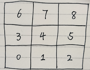
本人使用SimpleFoam计算方腔流,网格为3*3(这样好看矩阵的系数),如下加入的代码为压力修正方程系数的输出:
        fvScalarMatrix pEqn
        (
            fvm::laplacian(rAtU(), p)  == fvc::div(phiHbyA)
        );

        pEqn.setReference(pRefCell, pRefValue);

/////////////////////////////////////////////////////////////////////////////////////
/* */
	std::vector<std::vector<double>> P(mesh.nCells(), std::vector<double>(mesh.nCells(), 0.0));

    for(label i=0; i<mesh.nCells(); i++)
    {
       P[i][i] = pEqn.diag()[i];
    }

    for(label faceI=0; faceI<pEqn.lduAddr().lowerAddr().size(); faceI++)
    {
        label l = pEqn.lduAddr().lowerAddr()[faceI];
        label u = pEqn.lduAddr().upperAddr()[faceI];
        P[l][u] = pEqn.upper()[faceI];
        P[u][l] = pEqn.lower()[faceI];
    }


    Info << "P before boundary influence:\n" << endl;

    for (int i = 0; i < mesh.nCells(); i++)
    {
        Info << "[";
        for (int j = 0; j < mesh.nCells(); j++)
        {
            Info << P[i][j] << " ";
        }
        Info <<"]"<< endl;
    }
    Info << endl;
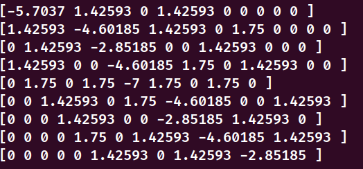
有意思的现象是 当我的pRefCell取网格单元0时,其矩阵系数如下

0号网格单元的对应的对角矩阵系数等于其余影响的单元系数负数之和的两倍(-5.7037 = -2*(1.42593+1.42593))
但是其余的网格单元对应的对角矩阵系数等于其余影响的单元系数之负和
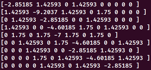
如果将pRefCell选为1时,那么矩阵系数如下

有意思的点来了,1号网格单元的对应的对角矩阵系数等于其余影响的单元系数负数之和的两倍(-9.2037 = -2*(1.42593+1.42593+1.75))
其余的网格单元对应的对角矩阵系数等于其余影响的单元系数之负和
有大佬知道为什么这么处理吗?
@lwjetmann 在 极低雷诺数下,PIMPLE迭代初始残差保持为1,降不下来 中说:
@李东岳 感觉这个问题挺有意义的,肯定可以从原理上说清楚为啥发散。给的是一个极大的单块网格平动(入口速度零,零法向压力梯度;出口压力零,零速度梯度),一直调不出来就放弃了,可能雷诺数低到某个程度,就不能靠放大计算域来使边界条件匹配了。
祝李老师上课愉快!
老哥,这个问题最后解决了吗
@李东岳 在 关于interFoam中对应k-epsilon湍流模型公式的问题 中说:
alpha跟rho是分开的,你不能写到一起,rho=alpha1rho1+alpha2rho2, alpha是alpha
李老师好,这个alpha指的是某一相的体积分数吗?k和epsilon的控制方程中使用$\alpha \rho$是有什么特定物理意义吗?(如果有相应推导的文章就更好了)
各位大佬,在OpenFOAM中的k-epsilon湍流模型k,和epsilon对应的公式是这样的:


这里的 $\alpha\rho$是否代表
$$\alpha\rho = \alpha\rho_l + (1-\alpha)\alpha_g$$
如果$\alpha$表示含液率的话?
各位老哥好,有个小问题,我目前现在计算域中取一个矩形平面区域,这个矩形平面用于注入粒子,有没有相关的InjectionModel呢?
各位大佬好,我看到一篇使用Fluent模拟多相流的论文,使用的VOF模型,设置的边界条件为质量流量边界条件,我的模拟主要借助OpenFOAM的VOF方法(interFoam求解器),OpenFOAM中关于VOF方法的多相流模拟需要初始化体积分数场和速度场。
所以我比较想了解,Fluent中如果设置了两种流体的质量流量,那么是怎么通过这两个质量流量来设置体积分数场和速度场的边界条件呢?(两种流体都是不可压缩流体)
lnInclude文件夹中有这个BlendedInterfacialModel.H文件的链接吗?
 我这出现了这个错误,想问问李老师这个问题怎么解决呢?
@李东岳 这个我尝试过调节simpleGrading (1 1 1),但是报错了。好像是因为我分为了五个块

我想问问老师,除了上面这个图的地方还需要改动哪些地方呀?
@李东岳 李老师好,我想要加入湍流模型,比如k-epsilon,所以需要对壁面加入边界层,blockMeshDict中有专门添加边界层的模块字典吗?
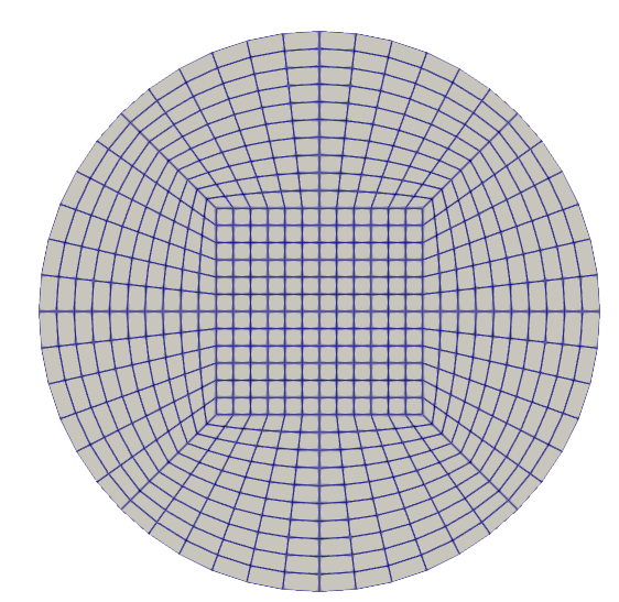
各位大佬好,我通过如下的blockMesh生成了一个圆柱型网格(O型切分),但想针对壁面wallPipe添加5层边界层进行湍流模拟,我使用的blockMeshDict和snappyHexMeshDict文件如下,blockMesh可以生成较好的网格,但是使用snappyHexMesh -overwrite命令后,网格没有任何变化,想请教各位,OpenFOAM有没有其他添加边界层的方法呢?或者我目前的方法有什么问题?
/*--------------------------------*- C++ -*----------------------------------*\
| =========                 |                                                 |
| \\      /  F ield         | OpenFOAM: The Open Source CFD Toolbox           |
|  \\    /   O peration     | Version:  5                                     |
|   \\  /    A nd           | Web:      www.OpenFOAM.org                      |
|    \\/     M anipulation  |                                                 |
\*---------------------------------------------------------------------------*/
FoamFile
{
    version     2.0;
    format      ascii;
    class       dictionary;
    object      blockMeshDict;
}
// * * * * * * * * * * * * * * * * * * * * * * * * * * * * * * * * * * * * * //

convertToMeters 1;

trueradius 0.025;

radius      #calc "sqrt(2.0)*0.5*$trueradius";//圆柱半径
radiusNeg   #calc "-sqrt(2.0)*0.5*$trueradius";
box         0.0092; // boxNeg定义中间长方体block的范围    0.12
boxNeg     -0.0092;
zMax        0.5;//100;//zMax和zMin定义圆柱体的长度
zMin        0.0;

nR          10;//扇形block半径上的节点数          6
nBox        12;//矩形block正方形边上的节点数     8
nZ          180;//5000;//轴向方向上的节点数


verbose no;

geometry
{
    cylinder
    {
        type      searchableCylinder;
        point1    (0 0 -0.1);//由point1和point2构成的区域要大于zMax和zMin构成的区域
        point2    (0 0  1000.1);//100.1);
        radius    $trueradius;
    }
}

scale 1;


vertices
(
    // Inner
    ($boxNeg $boxNeg $zMin)//0
    ($box    $boxNeg $zMin)//1
    ($boxNeg $box    $zMin)//2
    ($box    $box    $zMin)//3

    // Outer block points
    project ($radiusNeg $radiusNeg $zMin) (cylinder)//4
    project ($radius    $radiusNeg $zMin) (cylinder)//5
    project ($radiusNeg $radius    $zMin) (cylinder)//6
    project ($radius    $radius    $zMin) (cylinder)//7

    // Inner
    ($boxNeg $boxNeg $zMax)//8
    ($box    $boxNeg $zMax)//9
    ($boxNeg $box    $zMax)//10
    ($box    $box    $zMax)//11

    // Outer block points
    project ($radiusNeg $radiusNeg $zMax) (cylinder)//12
    project ($radius    $radiusNeg $zMax) (cylinder)//13
    project ($radiusNeg $radius    $zMax) (cylinder)//14
    project ($radius    $radius    $zMax) (cylinder)//15
);

blocks
(
    hex ( 4  5  1  0 12 13  9  8) ($nBox $nR   $nZ) simpleGrading (1 1 1)
    hex ( 4  0  2  6 12  8 10 14) ($nR   $nBox $nZ) simpleGrading (1 1 1)
    hex ( 1  5  7  3  9 13 15 11) ($nR   $nBox $nZ) simpleGrading (1 1 1)
    hex ( 2  3  7  6 10 11 15 14) ($nBox $nR   $nZ) simpleGrading (1 1 1)
    hex ( 0  1  3  2  8  9 11 10) ($nBox $nBox $nZ) simpleGrading (1 1 1)
);

edges
(
    project  4  5 (cylinder)
    project  7  5 (cylinder)
    project  6  7 (cylinder)
    project  4  6 (cylinder)
    project 12 13 (cylinder)
    project 13 15 (cylinder)
    project 12 14 (cylinder)
    project 14 15 (cylinder)
);

boundary
(
    bottom
    {
    	type patch;  // patch
    	faces
    	(
	     (0 1 3 2)
	     (0 2 6 4)
	     (0 1 5 4)
	     (1 5 7 3)
	     (2 3 7 6)
	);
    }

    outlet
    {
    	type patch;  // patch
    	faces
    	(
	     (8   9  11  10)
	     (8  10  14  12)
	     (8   9  13  12)
	     (9  13  15  11)
	     (10 11  15  14)
	);
    }

    wallPipe
    {
    	type wall;
    	faces
    	(
	     (4  12  14  6)
	     (4   5  13 12)
	     (5  13  15  7)
	     (6   7  15 14)
	);
    }
);

mergePatchPairs
(
);


// ************************************************************************* //
snappyHexMeshDict文件
/*--------------------------------*- C++ -*----------------------------------*\
| =========                 |                                                 |
| \\      /  F ield         | OpenFOAM: The Open Source CFD Toolbox           |
|  \\    /   O peration     | Version:  v2206                                 |
|   \\  /    A nd           | Website:  www.openfoam.com                      |
|    \\/     M anipulation  |                                                 |
\*---------------------------------------------------------------------------*/
FoamFile
{
    version     2.0;
    format      ascii;
    class       dictionary;
    object      snappyHexMeshDict;
}
// * * * * * * * * * * * * * * * * * * * * * * * * * * * * * * * * * * * * * //

// Which of the steps to run
castellatedMesh false;
snap            false;
addLayers       true;


// Geometry. Definition of all surfaces. All surfaces are of class
// searchableSurface.
geometry
{}


// Settings for the castellatedMesh generation.
castellatedMeshControls
{

    // Refinement parameters
    // ~~~~~~~~~~~~~~~~~~~~~

    // If local number of cells is >= maxLocalCells on any processor
    // switches from from refinement followed by balancing
    // (current method) to (weighted) balancing before refinement.
    maxLocalCells 100000;

    // Overall cell limit (approximately). Refinement will stop immediately
    // upon reaching this number so a refinement level might not complete.
    // Note that this is the number of cells before removing the part which
    // is not 'visible' from the keepPoint. The final number of cells might
    // actually be a lot less.
    maxGlobalCells 2000000;

    // The surface refinement loop might spend lots of iterations refining just a
    // few cells. This setting will cause refinement to stop if <= minimumRefine
    // are selected for refinement. Note: it will at least do one iteration
    // (unless the number of cells to refine is 0)
    minRefinementCells 0;

    // Allow a certain level of imbalance during refining
    // (since balancing is quite expensive)
    // Expressed as fraction of perfect balance (= overall number of cells /
    // nProcs). 0=balance always.
    maxLoadUnbalance 0.10;

    // Number of buffer layers between different levels.
    // 1 means normal 2:1 refinement restriction, larger means slower
    // refinement.
    nCellsBetweenLevels 1;


    // Explicit feature edge refinement
    // ~~~~~~~~~~~~~~~~~~~~~~~~~~~~~~~~

    // Specifies a level for any cell intersected by explicitly provided
    // edges.
    // This is a featureEdgeMesh, read from constant/triSurface for now.
    // Specify 'levels' in the same way as the 'distance' mode in the
    // refinementRegions (see below). The old specification
    //      level   2;
    // is equivalent to
    //      levels  ((0 2));

    features
    ();


    // Surface based refinement
    // ~~~~~~~~~~~~~~~~~~~~~~~~

    // Specifies two levels for every surface. The first is the minimum level,
    // every cell intersecting a surface gets refined up to the minimum level.
    // The second level is the maximum level. Cells that 'see' multiple
    // intersections where the intersections make an
    // angle > resolveFeatureAngle get refined up to the maximum level.

    refinementSurfaces
    {}

    // Feature angle:
    // - used if min and max refinement level of a surface differ
    // - used if feature snapping (see snapControls below) is used
    resolveFeatureAngle 30;


    // Region-wise refinement
    // ~~~~~~~~~~~~~~~~~~~~~~

    // Specifies refinement level for cells in relation to a surface. One of
    // three modes
    // - distance. 'levels' specifies per distance to the surface the
    //   wanted refinement level. The distances need to be specified in
    //   increasing order.
    // - inside. 'levels' is only one entry and only the level is used. All
    //   cells inside the surface get refined up to the level. The surface
    //   needs to be closed for this to be possible.
    // - outside. Same but cells outside.

    refinementRegions
    {}

    // Mesh selection
    // ~~~~~~~~~~~~~~

    // After refinement patches get added for all refinementSurfaces and
    // all cells intersecting the surfaces get put into these patches. The
    // section reachable from the location(s)InMesh is kept.
    // NOTE: This point should never be on a face, always inside a cell, even
    // after refinement.
    //
    // There are two different ways of specifying the regions to keep:
    // 1. a single locationInMesh. All the 'zoned' surfaces are marked as such
    //    in the refinementSurfaces with the faceZone and cellZone keywords.
    //
    // or
    //
    // 2. multiple locationsInMesh, with per location the name of the cellZone.
    //    This uses walking to determine zones and automatically creates
    //    faceZones on the outside of cellZones.


    // Ad 1. Specify a single location and how to treat faces inbetween
    //       cellZones
    locationInMesh (5 0.28 0.43);

    // Whether any faceZones (as specified in the refinementSurfaces)
    // are only on the boundary of corresponding cellZones or also allow
    // free-standing zone faces. Not used if there are no faceZones.
    allowFreeStandingZoneFaces true;
}


// Settings for the snapping.
snapControls
{
    // Number of patch smoothing iterations before finding correspondence
    // to surface
    nSmoothPatch 3;

    // Maximum relative distance for points to be attracted by surface.
    // True distance is this factor times local maximum edge length.
    // Note: changed(corrected) w.r.t 1.7.x! (1.7.x used 2* tolerance)
    tolerance 2.0;

    // Number of mesh displacement relaxation iterations.
    nSolveIter 30;

    // Maximum number of snapping relaxation iterations. Should stop
    // before upon reaching a correct mesh.
    nRelaxIter 5;

}


// Settings for the layer addition.
addLayersControls
{
    // Are the thickness parameters below relative to the undistorted
    // size of the refined cell outside layer (true) or absolute sizes (false).
    relativeSizes false;

    // Layers defined by overall thickness and expansion ratio
//    thickness           0.7e-3;
    firstLayerThickness 2e-3;
	expansionRatio 1.2;

    // Minimum overall thickness of total layers. If for any reason layer
    // cannot be above minThickness do not add layer.
    // If relativeSizes this is relative to undistorted size of cell
    // outside layer..
    minThickness 0.0001e-3;


    // Per final patch (so not geometry!) the layer information
    layers
    {
        sidewalls
        {
            nSurfaceLayers 3;
        }

    }

    // If points get not extruded do nGrow layers of connected faces that are
    // also not grown. This helps convergence of the layer addition process
    // close to features.
    // Note: changed(corrected) w.r.t 1.7.x! (didn't do anything in 1.7.x)
    nGrow 0;

    // Advanced settings


    // Static analysis of starting mesh

        // When not to extrude surface. 0 is flat surface, 90 is when two faces
        // are perpendicular
        featureAngle 130;

        // When to merge patch faces. Default is featureAngle
        //mergePatchFacesAngle 45;

        // Do not extrude around sharp edge if not both faces are extruded.
        // Default is 0.5*featureAngle. Set to -180 always attempt extrusion
        layerTerminationAngle -180;

        // Stop layer growth on highly warped cells
        maxFaceThicknessRatio 0.5;


    // Patch displacement

        // Number of smoothing iterations of surface normals
        nSmoothSurfaceNormals 1;

        // Smooth layer thickness over surface patches
        nSmoothThickness 10;


    // Medial axis analysis

        // Angle used to pick up medial axis points
        // Note: changed(corrected) w.r.t 1.7.x! 90 degrees corresponds to 130
        // in 1.7.x.
        minMedialAxisAngle 90;

        // Reduce layer growth where ratio thickness to medial
        // distance is large
        maxThicknessToMedialRatio 0.3;

        // Number of smoothing iterations of interior mesh movement direction
        nSmoothNormals 3;

        // Optional: at non-patched sides allow mesh to slip if extrusion
        // direction makes angle larger than slipFeatureAngle. Default is
        // 0.5*featureAngle.
        slipFeatureAngle 30;


    //// Motion solver instead of default medial axis
    //
    //    //- Use displacementMotionSolver to shrink mesh
    //    meshShrinker displacementMotionSolver;
    //
    //    //- Use laplacian for shrinking
    //    solver displacementLaplacian;
    //
    //    displacementLaplacianCoeffs
    //    {
    //        diffusivity quadratic inverseDistance ("m.*");
    //    }


    // Mesh shrinking

        // Maximum number of snapping relaxation iterations. Should stop
        // before upon reaching a correct mesh.
        nRelaxIter 5;

        // Create buffer region for new layer terminations
        nBufferCellsNoExtrude 0;

        // Overall max number of layer addition iterations. The mesher will
        // exit if it reaches this number of iterations; possibly with an
        // illegal mesh.
        nLayerIter 50;

        // Overall number of outer layer of iterations. Default is 1 -> all
        // layers are added in one pass.
        nOuterIter 3;
}

// Generic mesh quality settings. At any undoable phase these determine
// where to undo.
meshQualityControls
{
    // Specify mesh quality constraints in separate dictionary so can
    // be reused (e.g. checkMesh -meshQuality)
    #include "meshQualityDict"

    // Advanced

        // Number of error distribution iterations
        nSmoothScale 4;
        // amount to scale back displacement at error points
        errorReduction 0.75;
}


// Advanced

// Merge tolerance. Is fraction of overall bounding box of initial mesh.
// Note: the write tolerance needs to be higher than this.
mergeTolerance 1e-6;

debugFlags
(
    //mesh
);

// Write flags
writeFlags
(
    //layerFields     // write volScalarField for layer coverage
);

// ************************************************************************* //
blockMesh后生成的网格(俯视图)

不支持
@sxz0823 不支持,需要自己动手改代码