SnappyHexMesh中的使用问题
-
目前的问题主要是两方面:
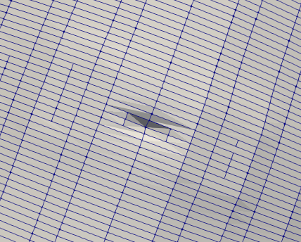
- 最终得到的贴体网格不够光滑,存在翘曲
2.边界层随缘加密,有时候能加上,有时候不能加上。
我个人的使用流程是这样的:
①用Solidwork画好实体,生成STL
②画背景网格并局部加密
③用surfaceFeatureExtract提取实体的边。
④SnappyHexMesh,将实体投射进网格。结果实际制作出来的网格是坑坑洼洼的,完全不光滑,例如...
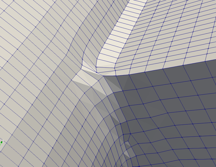
这样的效果还是在本人将Smooth和Snap的iteration调的非常大之后才能实现的,用200核的机器跑都需要15小时以上,然后跑出来结果就是这样的网格。
另外一个问题就是,我是的确选择了施加边界层的,但是到最后并没有出现边界层,依然只是局部加密。以下是我的SnappyHexMeshDict,不知有人愿意指点一下吗?谢谢
/*--------------------------------*- C++ -*----------------------------------*\ | ========= | | | \\ / F ield | OpenFOAM: The Open Source CFD Toolbox | | \\ / O peration | Version: plus | | \\ / A nd | Web: www.OpenFOAM.com | | \\/ M anipulation | | \*---------------------------------------------------------------------------*/ FoamFile { version 2.0; format ascii; class dictionary; object snappyHexMeshDict; } // * * * * * * * * * * * * * * * * * * * * * * * * * * * * * * * * * * * * * // // Which of the steps to run castellatedMesh true; snap true; addLayers true; geometry { body.stl { name floatingObject; type triSurfaceMesh; } }; // Settings for the castellatedMesh generation. castellatedMeshControls { // Refinement parameters // ~~~~~~~~~~~~~~~~~~~~~ // If local number of cells is >= maxLocalCells on any processor // switches from from refinement followed by balancing // (current method) to (weighted) balancing before refinement. maxLocalCells 100000; // Overall cell limit (approximately). Refinement will stop immediately // upon reaching this number so a refinement level might not complete. // Note that this is the number of cells before removing the part which // is not 'visible' from the keepPoint. The final number of cells might // actually be a lot less. maxGlobalCells 3000000; // The surface refinement loop might spend lots of iterations refining just a // few cells. This setting will cause refinement to stop if <= minimumRefine // are selected for refinement. Note: it will at least do one iteration // (unless the number of cells to refine is 0) minRefinementCells 50; // Allow a certain level of imbalance during refining // (since balancing is quite expensive) // Expressed as fraction of perfect balance (= overall number of cells / // nProcs). 0=balance always. maxLoadUnbalance 0.10; // Number of buffer layers between different levels. // 1 means normal 2:1 refinement restriction, larger means slower // refinement. nCellsBetweenLevels 2; // Explicit feature edge refinement // ~~~~~~~~~~~~~~~~~~~~~~~~~~~~~~~~ // Specifies a level for any cell intersected by explicitly provided // edges. // This is a featureEdgeMesh, read from constant/triSurface for now. // Specify 'levels' in the same way as the 'distance' mode in the // refinementRegions (see below). The old specification // level 2; // is equivalent to // levels ((0 2)); features ( { file "body.eMesh"; level 2; } ); // Surface based refinement // ~~~~~~~~~~~~~~~~~~~~~~~~ // Specifies two levels for every surface. The first is the minimum level, // every cell intersecting a surface gets refined up to the minimum level. // The second level is the maximum level. Cells that 'see' multiple // intersections where the intersections make an // angle > resolveFeatureAngle get refined up to the maximum level. refinementSurfaces { floatingObject { level (1 2); } } // Feature angle: // - used if min and max refinement level of a surface differ // - used if feature snapping (see snapControls below) is used resolveFeatureAngle 30; // Region-wise refinement // ~~~~~~~~~~~~~~~~~~~~~~ // Specifies refinement level for cells in relation to a surface. One of // three modes // - distance. 'levels' specifies per distance to the surface the // wanted refinement level. The distances need to be specified in // increasing order. // - inside. 'levels' is only one entry and only the level is used. All // cells inside the surface get refined up to the level. The surface // needs to be closed for this to be possible. // - outside. Same but cells outside. refinementRegions { floatingObject { mode distance; levels ((2 2) (4 1)); } } // Mesh selection // ~~~~~~~~~~~~~~ // After refinement patches get added for all refinementSurfaces and // all cells intersecting the surfaces get put into these patches. The // section reachable from the locationInMesh is kept. // NOTE: This point should never be on a face, always inside a cell, even // after refinement. locationInMesh (0.0 0.0 0.1); // Whether any faceZones (as specified in the refinementSurfaces) // are only on the boundary of corresponding cellZones or also allow // free-standing zone faces. Not used if there are no faceZones. allowFreeStandingZoneFaces true; } // Settings for the snapping. snapControls { // Number of patch smoothing iterations before finding correspondence // to surface nSmoothPatch 120; // Maximum relative distance for points to be attracted by surface. // True distance is this factor times local maximum edge length. // Note: changed(corrected) w.r.t 17x! (17x used 2* tolerance) tolerance 2.0; // Number of mesh displacement relaxation iterations. nSolveIter 300; // Maximum number of snapping relaxation iterations. Should stop // before upon reaching a correct mesh. nRelaxIter 80; // Feature snapping // Number of feature edge snapping iterations. // Leave out altogether to disable. nFeatureSnapIter 80; // Detect (geometric only) features by sampling the surface // (default=false). implicitFeatureSnap true; // Use castellatedMeshControls::features (default = true) explicitFeatureSnap true; // Detect features between multiple surfaces // (only for explicitFeatureSnap, default = false) multiRegionFeatureSnap false; } // Settings for the layer addition. addLayersControls { // Are the thickness parameters below relative to the undistorted // size of the refined cell outside layer (true) or absolute sizes (false). relativeSizes false; // Layer thickness specification. This can be specified in one of four ways // - expansionRatio and finalLayerThickness (cell nearest internal mesh) // - expansionRatio and firstLayerThickness (cell on surface) // - overall thickness and firstLayerThickness // - overall thickness and finalLayerThickness // Expansion factor for layer mesh expansionRatio 1.2; // Wanted thickness of final added cell layer. If multiple layers // is the thickness of the layer furthest away from the wall. // Relative to undistorted size of cell outside layer. // See relativeSizes parameter. //finalLayerThickness 0.03; // Wanted thickness of the layer next to the wall. // If relativeSizes this is relative to undistorted size of cell // outside layer. //firstLayerThickness 0.3; // Wanted overall thickness of layers. // If relativeSizes this is relative to undistorted size of cell // outside layer. //thickness 0.2; // Minimum overall thickness of total layers. If for any reason layer // cannot be above minThickness do not add layer. // If relativeSizes this is relative to undistorted size of cell // outside layer.. minThickness 0.001; // Per final patch (so not geometry!) the layer information // Note: This behaviour changed after 21x. Any non-mentioned patches // now slide unless: // - nSurfaceLayers is explicitly mentioned to be 0. // - angle to nearest surface < slipFeatureAngle (see below) layers { floatingBody { nSurfaceLayers 8; firstLayerThickness 0.02; } } // If points get not extruded do nGrow layers of connected faces that are // also not grown. This helps convergence of the layer addition process // close to features. // Note: changed(corrected) w.r.t 17x! (didn't do anything in 17x) nGrow 0; // Advanced settings // When not to extrude surface. 0 is flat surface, 90 is when two faces // are perpendicular featureAngle 360; // At non-patched sides allow mesh to slip if extrusion direction makes // angle larger than slipFeatureAngle. //slipFeatureAngle 30; // Maximum number of snapping relaxation iterations. Should stop // before upon reaching a correct mesh. nRelaxIter 80; // Number of smoothing iterations of surface normals nSmoothSurfaceNormals 100; // Number of smoothing iterations of interior mesh movement direction nSmoothNormals 50; // Smooth layer thickness over surface patches nSmoothThickness 100; // Stop layer growth on highly warped cells maxFaceThicknessRatio 0.5; // Reduce layer growth where ratio thickness to medial // distance is large maxThicknessToMedialRatio 0.9; // Angle used to pick up medial axis points // Note: changed(corrected) w.r.t 17x! 90 degrees corresponds to 130 in 17x. minMedianAxisAngle 150; // Create buffer region for new layer terminations nBufferCellsNoExtrude 0; // Overall max number of layer addition iterations. The mesher will exit // if it reaches this number of iterations; possibly with an illegal // mesh. nLayerIter 80; // Max number of iterations after which relaxed meshQuality controls // get used. Up to nRelaxIter it uses the settings in meshQualityControls, // after nRelaxIter it uses the values in meshQualityControls::relaxed. nRelaxedIter 80; // Additional reporting: if there are just a few faces where there // are mesh errors (after adding the layers) print their face centres. // This helps in tracking down problematic mesh areas. //additionalReporting true; } // Generic mesh quality settings. At any undoable phase these determine // where to undo. meshQualityControls { // Maximum non-orthogonality allowed. Set to 180 to disable. maxNonOrtho 70; // Max skewness allowed. Set to <0 to disable. maxBoundarySkewness 4; maxInternalSkewness 4; // Max concaveness allowed. Is angle (in degrees) below which concavity // is allowed. 0 is straight face, <0 would be convex face. // Set to 180 to disable. maxConcave 80; // Minimum pyramid volume. Is absolute volume of cell pyramid. // Set to a sensible fraction of the smallest cell volume expected. // Set to very negative number (e.g. -1E30) to disable. minVol 1e-13; // Minimum quality of the tet formed by the face-centre // and variable base point minimum decomposition triangles and // the cell centre. This has to be a positive number for tracking // to work. Set to very negative number (e.g. -1E30) to // disable. // <0 = inside out tet, // 0 = flat tet // 1 = regular tet minTetQuality 1e-15; // Minimum face area. Set to <0 to disable. minArea -1; // Minimum face twist. Set to <-1 to disable. dot product of face normal // and face centre triangles normal minTwist -2; // minimum normalised cell determinant // 1 = hex, <= 0 = folded or flattened illegal cell minDeterminant 0.001; // minFaceWeight (0 -> 0.5) minFaceWeight 0.00; // minVolRatio (0 -> 1) minVolRatio 0.01; // must be >0 for Fluent compatibility minTriangleTwist -1; //- If >0 : preserve single cells with all points on the surface if the // resulting volume after snapping (by approximation) is larger than // minVolCollapseRatio times old volume (i.e. not collapsed to flat cell). // If <0 : delete always. //minVolCollapseRatio 0.5; // Advanced // Number of error distribution iterations nSmoothScale 200; // amount to scale back displacement at error points errorReduction 0.8; // Optional : some meshing phases allow usage of relaxed rules. // See e.g. addLayersControls::nRelaxedIter. relaxed { //- Maximum non-orthogonality allowed. Set to 180 to disable. maxNonOrtho 70; } } // Advanced // Merge tolerance. Is fraction of overall bounding box of initial mesh. // Note: the write tolerance needs to be higher than this. mergeTolerance 1e-6; // ************************************************************************* // -
个人的一个经验是善用refinementRegions关键字,在需要加密的地方建立refinementRegions,将level提高些,应该可以优化一下网格。还有一个地方是可以试试调整surfaceFeatureDict中的includedAngle,可以优化角度变化比较剧烈处的网格,比如你第一张图那里。另外可以适当将maxLocalCells和maxGlobalCells提高些。这个还是熟能生巧,多试试改变那些参数。
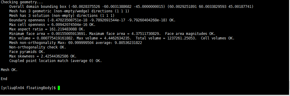
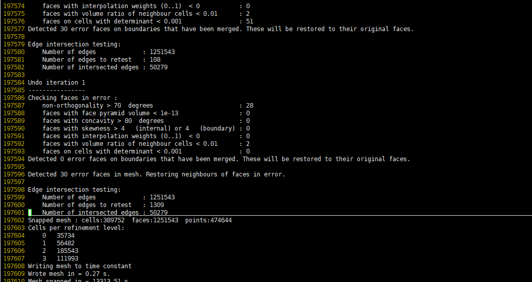
SHM是分步来处理网格的,先是snap,最后才是加边界层。所以边界层网格在最后一个时间步内,不知道你有没有查看最后一个时间步的网格。 -
@chaoscfd
这里想请问您几个问题:- 建立refineRegions,我这里是用distance的办法定义的refineRegion,离模型xx米内用xx等级这样,我还需要另外用box对其局部定义吗? 还是说我只需要提高distance的等级就可以了?
2.第二就是includeAngle,我这里取得是90°,我之前尝试过取180°,的确新选取的边很多都是我想要的,但是也出现了好多我不想要的edge(比如明明就是个连续的面,结果突然出现一个edge斜着贯穿了这个面,类似一个正方型强行被分成2个三角形)。有没有什么办法,只捕捉到我想优化的edge,而抛弃一些莫名其妙捕捉到的edge呢
- 建立refineRegions,我这里是用distance的办法定义的refineRegion,离模型xx米内用xx等级这样,我还需要另外用box对其局部定义吗? 还是说我只需要提高distance的等级就可以了?