dynamic and static mesh 相结合问题 (pointwise生成网格)
-
各位好,
本人刚开始做动网格的数值模拟问题,想用interPhaseChangeDymFoam solver 来模拟流动问题。最近看了movingCone 和propeller 这二个OpenFOAM自带的例子。可是对其中的细节还不了解。。。
我用修改的movingCone这例子来解释我想要做的模拟。原本的例子在movingWall动起来之后整个流场的网格都在动,我想把流场分成2部分,movingWall只在其中一个zone运动,另一个区域里的网格不动。
我想用pointwise来生成整个网格。。。请问各位有推荐的帖子和算例么。。。
谢谢

-
@walli1986 在 dynamic and static mesh 相结合问题 (pointwise生成网格) 中说:
原本的例子在movingWall动起来之后整个流场的网格都在动,我想把流场分成2部分,movingWall只在其中一个zone运动,另一个区域里的网格不动。
目前你需要自己写代码实现相关的功能。默认是全场网格点的运动。可以设置不同的区域,仅仅移动某些区域内的点。
-
@walli1986 这个比较复杂,我们以前准备重叠网格先用第三方软件单独生成背景网格和物体网格,然后使用
mergeMeshes命令,再结合一串辅助命令最后再配置好zone就可以使用了。我贴一个我们以前一个算例的代码#!/bin/sh # Source tutorial run functions . $WM_PROJECT_DIR/bin/tools/RunFunctions mkdir constant cp -rf bodyMesh/constant/polyMesh constant mergeMeshes .. case_01 . backgroundMesh rm -rf constant/polyMesh mv 0.*/polyMesh constant rm -rf 0.* rm -f constant/polyMesh/pointZones constant/polyMesh/pointZones.gz constant/polyMesh/faceZones constant/polyMesh/faceZones.gz constant/polyMesh/cellZones constant/polyMesh/cellZones.gz # Make cell zones for all regions and clean up regionCellSets setSet -batch setBatch.batch rm -f constant/polyMesh/sets/*_old constant/polyMesh/sets/*_old.gz rm -f constant/polyMesh/sets/cellRegion0 constant/polyMesh/sets/cellRegion0.gz constant/polyMesh/sets/cellRegion1 constant/polyMesh/sets/cellRegion1.gz setsToZonessetBatch.batch文件cellSet sphere new cellToCell cellRegion0 cellSet background new cellToCell cellRegion1 cellSet cellRegion0 delete cellSet cellRegion1 delete quittopoSetDict文件:actions ( { name c0; type cellSet; action new; source sphereToCell; sourceInfo { centre (0 0 0); radius 0.03499999; } } { name c0; type cellSet; action invert; } { name c0; type cellSet; action delete; } );不过现在我们只使用
STAR CCM+,网格转换很快捷,以plus系列为例,只要运行ccmToFoam <ccm-file>就可以了,动网格就再加一个setFields。 -
@walli1986 把你的速度函数离散化,然后用
table就可以了。
table: inline list of(time value)pairs; interpolates valueslinearlybetween times.
(from https://cfd.direct/openfoam/user-guide/v6-boundaries/) -
@队长别开枪 @东岳
十分感谢您的指点,我现在会正确设置网格移动的方向和距离了。这个论坛真的给我们提供了一个学习的好地方。
现在想请教一个网格的问题,不知道是在这里接着发好,还是另发一个贴好。
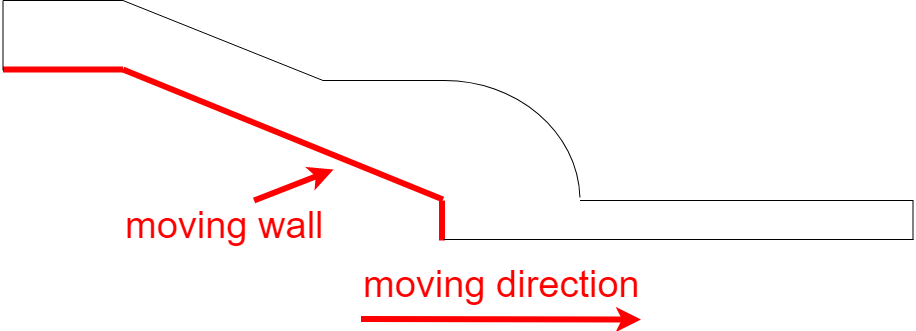
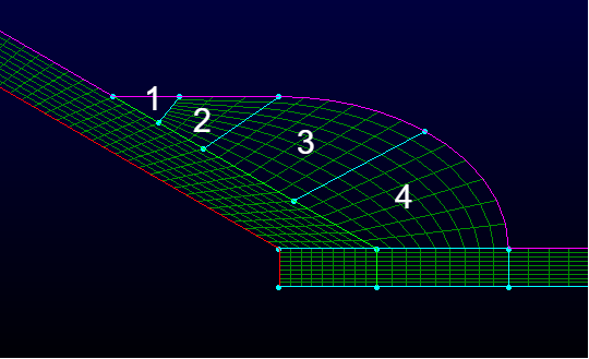
第一个图显示计算模型的示意图,红色的是移动边界,但只向右边移动。。。第二个图是我画的一个很粗糙的网格,目的就是想看看怎样进行网格分布。我把动网格移动的区域弄成沿着水平方向规则的网格。那些标记为1,2,3,4的区域是我单独分开的。现在看起来 2,3,4 的网格还行。 就是不知道怎么画 1 处的网格。
各位有更好的方法来划分区域么?


