使用SimpleFoam求解器模拟单管流动问题时速度剖面与泊肃叶方程理论计算出现偏差【萌新求助】
-
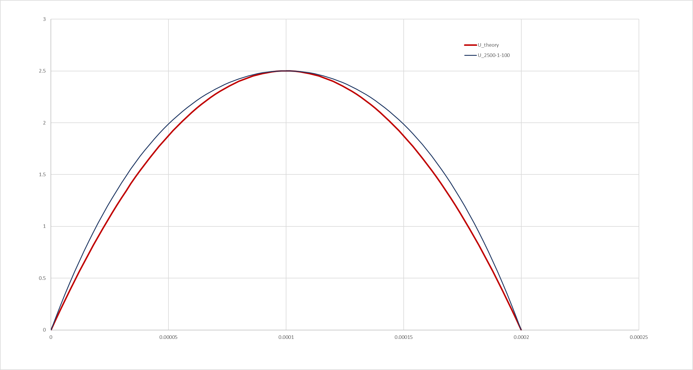
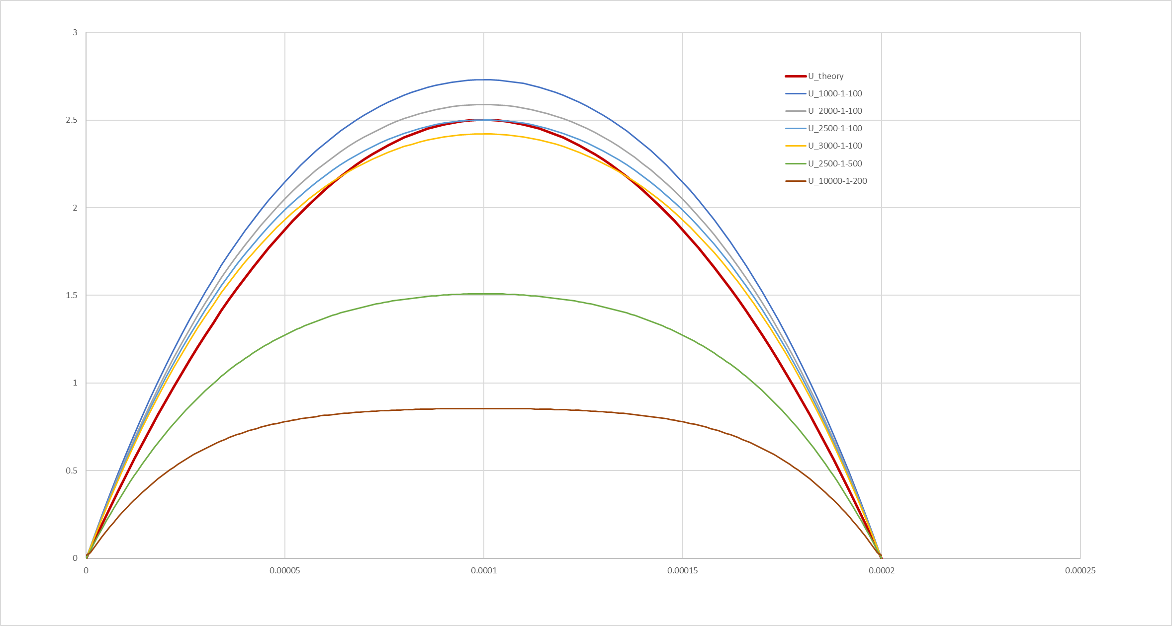
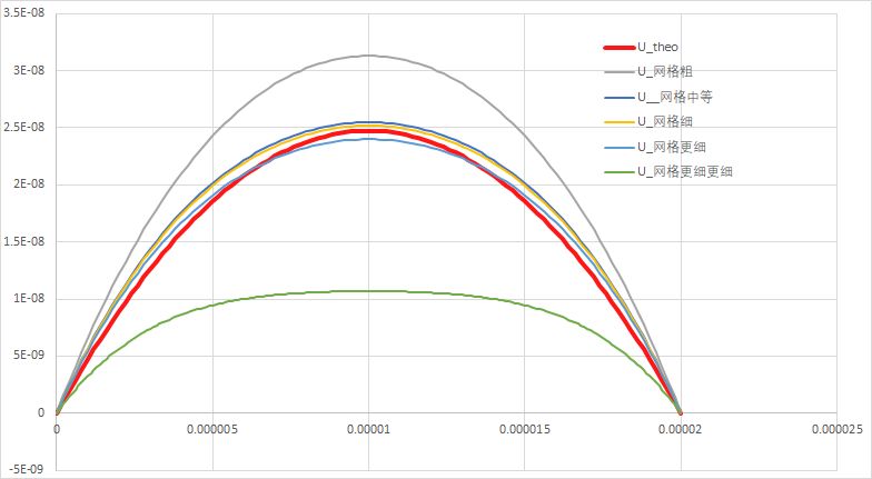
大家好!最近在用SimpleFoam模拟了一个单管流动的二维的速度剖面问题,一开始没有出现抛物线的速度剖面,学习了 @热爱CFD的卡卡 当时20年的帖子更新了粘度和尺寸出现了抛物线的速度剖面(感谢感谢)。我对照分析了一下数据发现跟泊肃叶方程计算出来的理论值有一定的差异,并且这种差异还会随着网格尺寸的变化而改变,具体如下图所示(画的比较粗糙):
以下是建模过程:
【计算目标】计算半径为0.00001m,入口端压力为0.01kPa,出口端压力为0,运动粘度1e-2m2/s 的长0.001m,密度为水的密度,不考虑边界滑移条件的单管速度分布
【网格设置】blockMesh(这个应该是中等网格的算例)FoamFile { version 2.0; format ascii; class dictionary; object blockMeshDict; } scale 1e-5; vertices ( (0 0 0) // 0 (100 0 0) // 1 (100 0.1 0) // 2 (0 0.1 0) // 3 (0 0 2) // 4 (100 0 2) // 5 (100 0.1 2) // 6 (0 0.1 2) // 7 ); blocks ( hex (0 1 2 3 4 5 6 7)(2000 1 100) simpleGrading (1 1 1) ); edges ( ); boundary ( inlet { type patch; faces ( (0 3 7 4) ); } output { type patch; faces ( (1 2 6 5) ); } wall1 { type patch; faces ( (4 5 6 7) (0 1 2 3) ); } wall3 { type empty; faces ( (0 1 5 4) (3 2 6 7) ); } ); mergePatchPairs ( ); // ************************************************************************* //【求解设置】
FoamFile
{
    version     2.0;
    format      ascii;
    class       dictionary;
    object      fvSchemes;
}
// * * * * * * * * * * * * * * * * * * * * * * * * * * * * * * * * * * * * * //

ddtSchemes
{
    default         steadyState;
}

gradSchemes
{
    default         Gauss linear;
//     grad(U)         Gauss linear;
}

divSchemes
{
    default          Gauss upwind;

    div(phi,U)      bounded Gauss upwind;
    turbulence      bounded Gauss upwind;
    div(phi,k)      $turbulence;
    div(phi,epsilon) $turbulence;

    div((nuEff*dev2(T(grad(U))))) Gauss linear;
}
FoamFile { version 2.0; format ascii; class dictionary; object fvSolution; } // * * * * * * * * * * * * * * * * * * * * * * * * * * * * * * * * * * * * * // solvers { p { solver GAMG; tolerance 1e-06; relTol 0.1; smoother GaussSeidel; nPreSweeps 0; nPostSweeps 2; cacheAgglomeration on; agglomerator faceAreaPair; nCellsInCoarsestLevel 10; mergeLevels 1; } "(U|k|epsilon|R|nuTilda)" { solver smoothSolver; smoother symGaussSeidel; tolerance 1e-05; relTol 0.1; } } SIMPLE { nNonOrthogonalCorrectors 0; residualControl { p 1e-2; U 1e-3; "(k|epsilon)" 1e-4; } } relaxationFactors { fields { p 0.3; } equations { U 0.7; k 0.7; epsilon 0.7; } }【初始条件设置】采用压力边界驱动
压力FoamFile { version 2.0; format ascii; class volScalarField; object p; } // * * * * * * * * * * * * * * * * * * * * * * * * * * * * * * * * * * * * * // dimensions [0 2 -2 0 0 0 0]; internalField uniform 0; boundaryField { output { type fixedValue; value uniform 0; } inlet { type fixedValue; value uniform 0.01; } wall1 { type zeroGradient; } wall3 { type empty; } }速度
FoamFile
{
    version     2.0;
    format      ascii;
    class       volVectorField;
    location    "0.1";
    object      U;
}
// * * * * * * * * * * * * * * * * * * * * * * * * * * * * * * * * * * * * * //

dimensions      [0 1 -1 0 0 0 0];

internalField   uniform (0 0 0);
boundaryField
{
    output
    {
        type            zeroGradient;
    }
    inlet
    {
        type            zeroGradient;
    }

    wall1
    {
	type            noSlip;
    }
    wall3
    {
        type            empty;

    }
}
粘度
FoamFile
{
    version     2.0;
    format      ascii;
    class       dictionary;
    location    "constant";
    object      transportProperties;
}
// * * * * * * * * * * * * * * * * * * * * * * * * * * * * * * * * * * * * * //

transportModel  Newtonian;

nu               1e-02;
新人第一次发帖格式等不对之处还请大家多多包涵,这个问题还请大家不吝赐教!谢谢大家!
-
好的老师,我再调试调试

-
@ChangranLv
你这个曲线有一个明显的规律:网格越多,中心速度就越小。很大一个可能性是你的计算根本没有收敛。用simpleFoam 求解稳态问题,网格越多收敛会越慢,需要越多迭代步。